

Operating Elements
The figure below shows the tail of the MPO-500 and the most important operating elements.
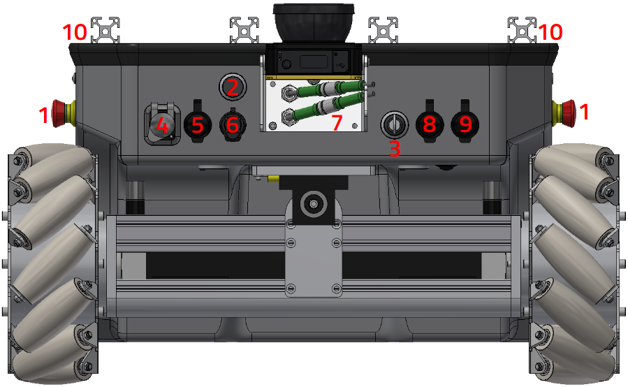
Operating elements of the MPO-500
1 Emergency stop buttons 2 Brake release button 3 Key switch 4 HDMI socket 5 Wireless joystick receiver 6 Charging socket 7 Connector for 2nd scanner 8 Ethernet socket 9 USB socket 10 LED indicators
Emergency Stop Buttons
When one of these buttons is pressed the robot is immediately set to emergency stop. All drives are disconnected from power supply and the fail-safe brakes are engaged. This state can be reset by unlocking the emergency stop buttons and turning the Key Switch clockwise to position II for a few seconds.
Key Switch
See Key Switch.
Brake Release Button
Pressing this button will open the motors’ brakes allowing the robot to be moved even while it is turned off.
Charging Socket
The battery charger can be manually connected to this socket. Further information can be found at Charging.
LED indicators
The MPO-500 comes with LED indicators similar to those used in the ROX series. You can find further information at LED Lighting.
Access to the On-Board Computer
An HDMI socket, a USB socket and an Ethernet port can be used to work on the computer and to prepare the robot for the next application.