

First Steps
This chapter describes the first steps to take your robot into operation for the first time. Following the steps below allows you to confirm the integrity of the robot’s hardware and software and to test its basic functionality.
Accessories and Preparations
Tip
In the documentation supplied with the robot, you will also find the access data for your personal customer area on our website. Individual documents and information on customised adjustments to your robot as well as the configuration files of all relevant components as they were on delivery are stored there. If you use PlatformPilot, you can also download the GTK GUI for setting up the robot here.
In addition to the mobile robot, you will also find a wired charger, various small parts and some documentation in the transport box. You will need the master key, the wireless gamepad and the WLAN access point to start up your robot for the first time.
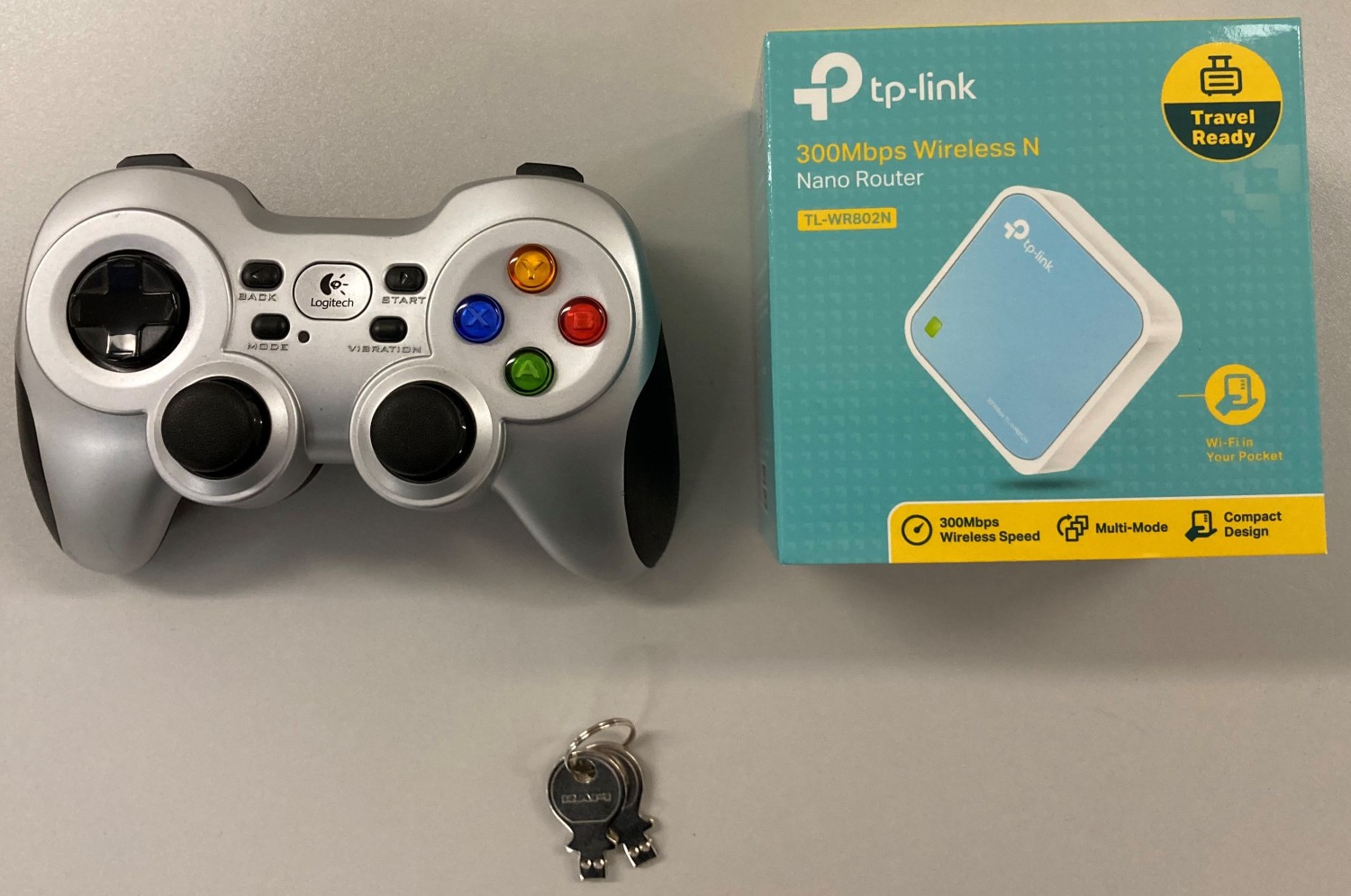
Unpack the access point and connect it to the power supply unit or to a USB port on your computer using the cable supplied. Optionally connect the access point to your company/home network via ethernet to enable internet access on the platform when needed.
The access point sets up an independent local WLAN network into which the robot automatically connects after start-up. The network name (SSID) and password can be found in the documentation supplied with the robot. You can connect to this network with any laptop and then communicate with the robot as described below.
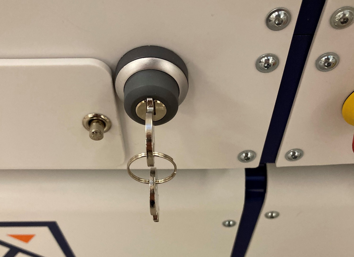
The key is used to switch the robot on and off and to release the safety system. For the first tests, simply insert it into the key switch. For regular operation, however, the key should not remain on the robot but should be under the supervision of a suitably qualified and trained operator who is responsible for the safe operation of the robot.
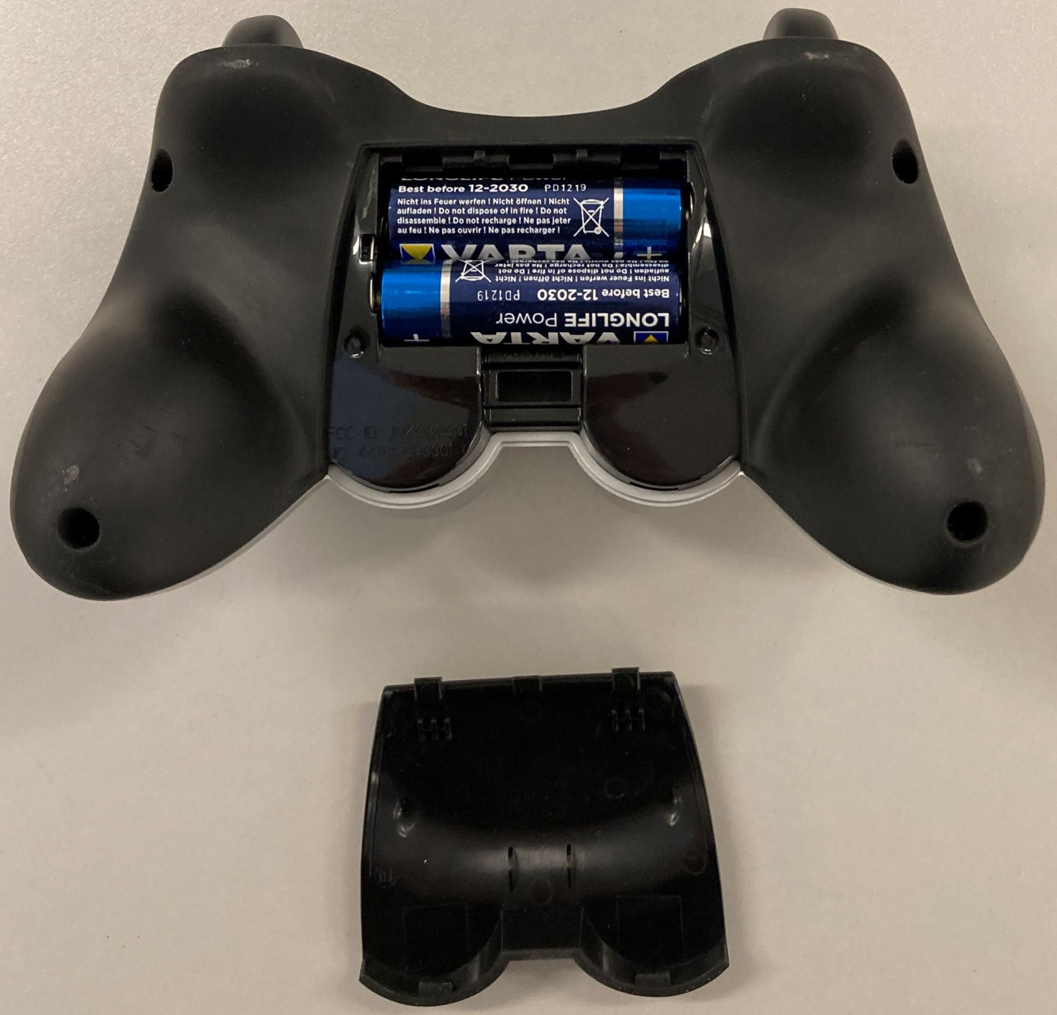
The gamepad batteries have either been insulated or removed for transport to prevent premature discharge. Open the battery compartment on the underside of the gamepad and insert the enclosed batteries or remove the insulating tape from the batteries before closing the compartment again.
Depending on the type of batteries used and the transport route, the batteries must first be reinstalled and connected after unpacking the robot. The exact procedure for this is described in the Maintenance chapter of the manual of your robot.
If your robot uses LiFePO4 batteries, they may need to be woken up from transport mode, as explained here. In any case, LiFePO4 batteries must first be activated by flipping the rocker switch next to the charging socket. Only then can the robot be switched on.
Starting up and Moving by Joystick
A detailed description of the controls and LED indicators can be found here.
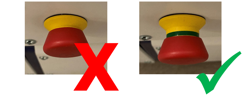
Before switching on the robot, unlock all emergency stop buttons by turning them. When the buttons are unlocked, a green band can be seen between the red mushroom button and the yellow base.
Turn the key switch clockwise to switch on the robot. If the robot has the optional radio emergency stop, this must be activated separately as described at Wireless Emergency Stop.
Robots with LED Indicators
After a few seconds you will hear the fan of the on-board computer start up and a little later the LED strips around the platform will light up. The robot first performs a self-test and cycles through all available colours before switching to the regular status indication. As soon as the robot lights up constantly in green, it is ready for use.
Robots with LC Display
The LCD will immediately light up, showing the basic status of the robot. After about one minute the display will show “Ready”. This means that the software has successfully started up and is able to communicate with all hardware components. You can find more information about the LCD here.
Please note that the MPO-700 and MMO-700 will perform a homing of the OmniDriveModules after start-up and before the robot is ready for operation. To do so all emergency stop buttons must be unlocked and the scanners’ safety fields must be clear of obstacles. All OmniDriveModules will slowly rotate around the vertical axis and then stop with the wheels facing outwards. The robot will stay in place during this procedure.
Joystick Usage
When not used for a while, the wireless gamepad goes into standby mode. To power it on, press any button (except MODE and VIBRATION). The green LED in the centre of the gamepad lights up briefly and indicates that a wireless connection to the robot platform has been established. If the LED blinks slowly instead, no connection could be established and the gamepad goes back into standby mode. In this case, please ensure that the platform PC is powered on, the wireless receiver is plugged into the PC and the radio transmission is not blocked or disturbed.
Tip
While the gamepad is powered on, you can quickly check the batteries by pressing the VIBRATION button. If you don’t feel a vibration, the battery charge is low or empty. You can also use this procedure to ensure that the gamepad is powered on, in case you missed the initial blink of the LED.
Note
Depending on the control software the gamepad has to be set to the correct mode via the small sliding switch at its front.
- When using PlatformPilot please switch to
X. - For ROS please use setting
D.
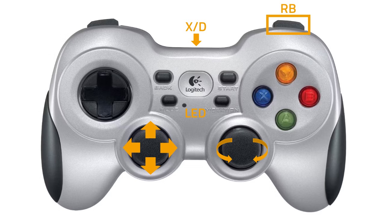
Press the blue X button to switch the robot to manual joystick mode. You can then move the robot using the two analogue sticks. The top right should button RB on the gamepad works as deadman switch. It must be pressed continuously for the robot to move.
- The left stick controls the translational movement, i.e. forwards and backwards movement on the Diff and Trike models, and movement in the plane on the omnidirectional Argo and Meca models.
- The right stick controls the turns, i.e. cornering and turning on the spot for Diff and Trike, and all superimposed turns at any time for Argo and Meca.
Warning
- On delivery, only the basic safety functions are active and only basic protective fields are configured. Depending on the environment, superstructure and speed, collisions are still possible. Please take appropriate care during your first driving attempts and adapt the safety configuration to your individual requirements as soon as possible!
- In joystick mode, predictive collision avoidance is not active and the safety system works purely reactively via the protective fields of the laser scanners. Automatic intelligent collision avoidance is only available in automatic mode.
Connecting the GUI
Connect your computer to the neo-training network set up by the access point as described above.
The default IP addresses of your mobile robots are 192.168.0.50 for the first one, 192.168.0.51 for the second one, and so on.
Please see the documentation that came with each platform to get a definite answer.
PlatformPilot-GUI
Open a web browser (we recommend Firefox) and enter http://192.168.0.50:8888 as the address. This address will take you to the WebGUI integrated in PlatformPilot and give you an immediate overview of the robot’s status.
For mapping and further setup of your application, please use the GTK GUI that you can download from your customer area on the Neobotix website.
Shutting Down the Robot
Robots with LED Indicators
To shut down your robot turn and hold the key in counter-clockwise direction. The LEDs will flash white to indicate that the shutdown signal has been detected. Hold the key in this position until the light stops flashing and turns to constant white instead. It will then slowly fade out until the robot switches itself off.
In case the robot uses LiFePO4 batteries and will probably not be used or charged for some time, please remember to deactivate the batteries as described here.
Robots with LC Display
To shut down your robot turn and hold the key for at least 3 seconds in counter-clockwise direction until the LC-Display shows that the shutdown has been triggered. Depending on the model of on-board computer the robot may switch itself off before the countdown has finished or simply when reaching zero.
Important Basic Settings
Depending on the location and the network infrastructure to be used, various settings may need to be made directly in the operating system of the on-board computer. All Neobotix robots offer the option of accessing the on-board computer directly via monitor and keyboard/mouse. However, VNC remote access is often faster and more convenient.
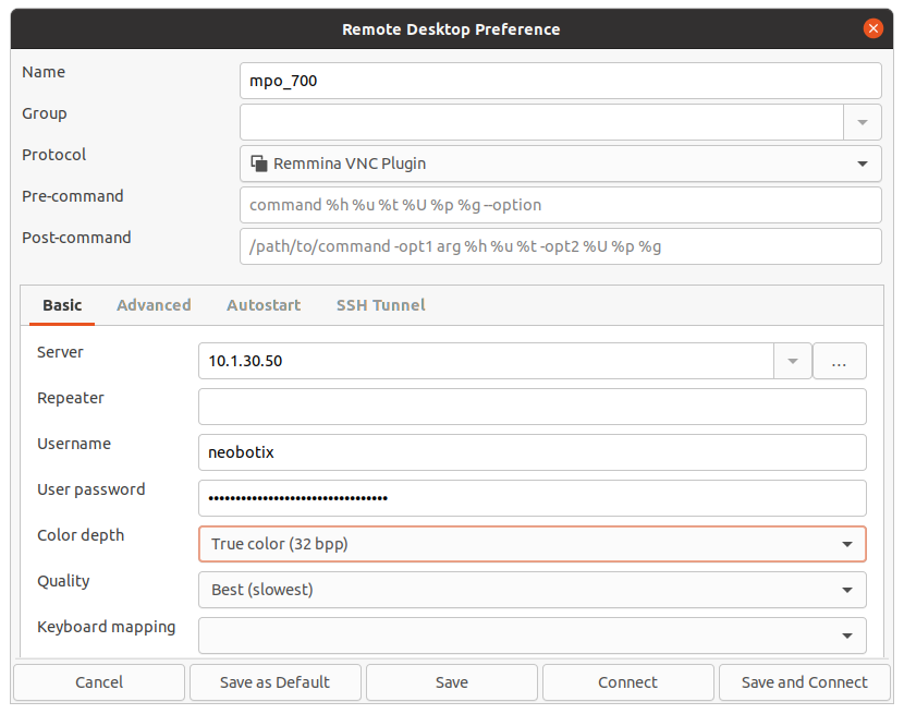
Remote Desktop Connection (VNC)
Once the platform has booted and your computer is connected to the same WLAN network you can connect to the robot using a software tool. The Remmina Remote Desktop Client should already be installed on most Ubuntu distributions. When using Windows we have had good experience with TightVNC.
System Time and Hardware Clock
By default the hardware clock is set to UTC and the time zone is set to Berlin. If you operate the platform in a different time zone it is necessary to change the time zone.
In addition the system time should always be set correctly if possible, since otherwise some functionality may not work properly (when connecting to the platform from another PC).
Automatic network time synchronization is disabled by default because it can cause the platform to fail during operation.
In order to adjust the time, it is best to first set the system time (which is only temporary) using
Xfce Settings >> Time and Date
and then synchronize the hardware clock to the current system time as follows:
sudo hwclock -w
Testing the Safe Position Detection
The ROX robots offer the option of safely confirming certain positions based on unique contours in the environment. This means that potentially risky actions and movements can be triggered at precisely those points where they are actually required and appropriately safeguarded. Incorrect release on a free route or at a random position can be ruled out.
Setting up this function for later use requires corresponding adjustments to the configuration and sequence control and can often only be carried out during the actual commissioning of the overall system. For this reason, ROX robots are delivered with an easy-to-reproduce configuration that only uses a simple box included in the scope of delivery as a reference. This means that the basic functionality can be easily reproduced and tested.
Preparations
Familiarise yourself with the basic operation of the ROX and set up automatic navigation. Move the robot to a test area with sufficient free space in front of the platform.
Build up the enclosed cardboard box and tape the top and bottom with parcel tape. Make sure that the glued flaps lie flat and that the box is stable and can stand upright without wobbling.
Two positions of the box relative to the robot are required, which are needed for different tests. It is important for both positions that the carton is placed parallel to the front of the robot and that its end face is in line with the left flank of the robot.

- Position 1 is used for the safe station approach.
The distance between the front of the robot and the carton (dimension
d1) should correspond to the length of the carton. - Position 2 simulates work at workstations, both by a cobot arm (safety mode HANDLING) and via other attachments such as roller conveyors (safety mode WORKING).
There should be a distance of approx. 2 cm between the box and the front emergency stop button (dimension
d2).
It has proven useful to temporarily mark the position of the robot as well as the carton position on the floor with adhesive tape. This means that the tests can be interrupted at any time and resumed later and are easily reproducible.
Note
The tolerance of the reference contour detection can be set individually for each field set in the configuration of the laser scanners. To simplify the initial tests, the tolerance for all field sets is set relatively generously at +/- 5 cm. Depending on the application and risk assessment, suitable values must be determined and configured individually.
The following sections will lead you through a cycle of steps where each step tests one of the safety features, namely
- safe station approach (from Position 1 to Position 2),
- safe working (at Position 2),
- safe handling (at Positon 2),
- safe station departure (from Position 2 to Position 1),
such that the last step will leave you in exactly the position that the tests were started from. The steps can either be executed manually by remote service calls or automatically by the supplied test script included with the robot software.
Testing the Safe Station Approach
If the robot has to move closer to a work station, machine or other object than the protective fields of the laser scanner would normally allow, the safe station approach can be used.
At a pre-position, Position 1 for these tests, the robot has to switch to safety mode APPROACHING which triggers the safe contour detection by the laser scanner. If the contour is successfully detected, the Flexi Soft safety controller reduces the protective field directly in front of the robot for a defined period of time, while also limiting the allowed velocity. During this time, the robot then can perform the approach, moving close to the box (Position 2).
Testing the Release of Working Devices
Some robots are designed for mounting additional devices for load transfer or for other tasks that may only be activated at defined positions for safety reasons. This ensures, for example, that heavy loads will not be dropped at random locations due to an error of the application sequence.
To test this feature, the robot must be in Position 2 and switch to safety mode WORKING. The safety controller tries to recognize the contour and, if successful, enables the working device. If the additional device has not already been fitted by Neobotix, the correct function is indicated by a small dummy relay on the platform, which must be replaced later. To get back to normal operation, switch to safety mode NONE. The test script will do this automatically after 10 seconds.
Testing the Enabling of Cobot Arms
With mobile manipulators, it must be ensured that the integrated cobot arm can only be activated and moved when the mobile platform is stationary and in the correct location. Otherwise, it could happen that the arm performs movements in an area that is not covered by the protective fields of the laser scanners because there should actually be a machine or another object with which the arm should interact. If this were to happen in an open area due to an error in the sequence control, people could step into the arm’s range and be injured.
To test this feature, the robot must be in Position 2 and switch to safety mode HANDLING. The safety controller tries to recognize the contour and, if successful, revokes the safe stop of the arm so that it can move. With most Cobot arms, the current status can be easily recognised on the hand-held control unit. To get back to normal operation, switch to safety mode NONE. The test script will do this automatically after 10 seconds.
Tip
If the arm is moved and is not returned to the safe home position, it is no longer possible to move the platform after switching back to normal operation. The arm must first be moved back into the safe home position. Further information on this can be found in the ROX Security Functions document in your customer area.
Testing the Departure From a Work Station
If the robot is close to a workstation, normal driving attempts may result in the workstation being immediately recognised as an obstacle that is too close, triggering a protective field violation and therefore preventing movement. For these cases, there is the DEPARTING safety mode, which works in exactly the opposite way to APPROACHING.
For this test setup, the robot has to be in Position 2 and switch to safety mode DEPARTING. If the box is recognized in the correct position, the protective fields are reduced for a defined period of time and the allowed velocity is limited. During this time, the robot can depart from the box and move back to Position 1.