Starting with ROS on the Simulation
The simulation package neo_simulation2, comes along with all the new ROS 2 features. Like it’s predecessor, neo_simulation2 package is fully equipped with all the Neobotix robots that is available in the market. By combining the novelty of ROS 2 and the state-of-the-art Neobotix platforms would allow the users to learn and develop various reliable and robust application that caters their needs in both the research and as well as in industries.
Configuration and Launch
Configuration
Setup environment variables
1. Select the robot (default mpo_700)
export MY_ROBOT=mpo_700
- Select the world
export MAP_NAME=neo_workshop
Available Parameters
You can read about the details of the robot in our official website
| MY_ROBOT | mpo_700, mpo_500, mp_400, mp_500 |
Please go down to see the available worlds.
| MY_ROBOT_WORLD | neo_track1.world neo_track2.world neo_workshop.world |
Launch
Launching the simulation is fairly easy
Just use the simulation.launch.py file that we configured in the chapter above.
ros2 launch neo_simulation2 simulation.launch.py
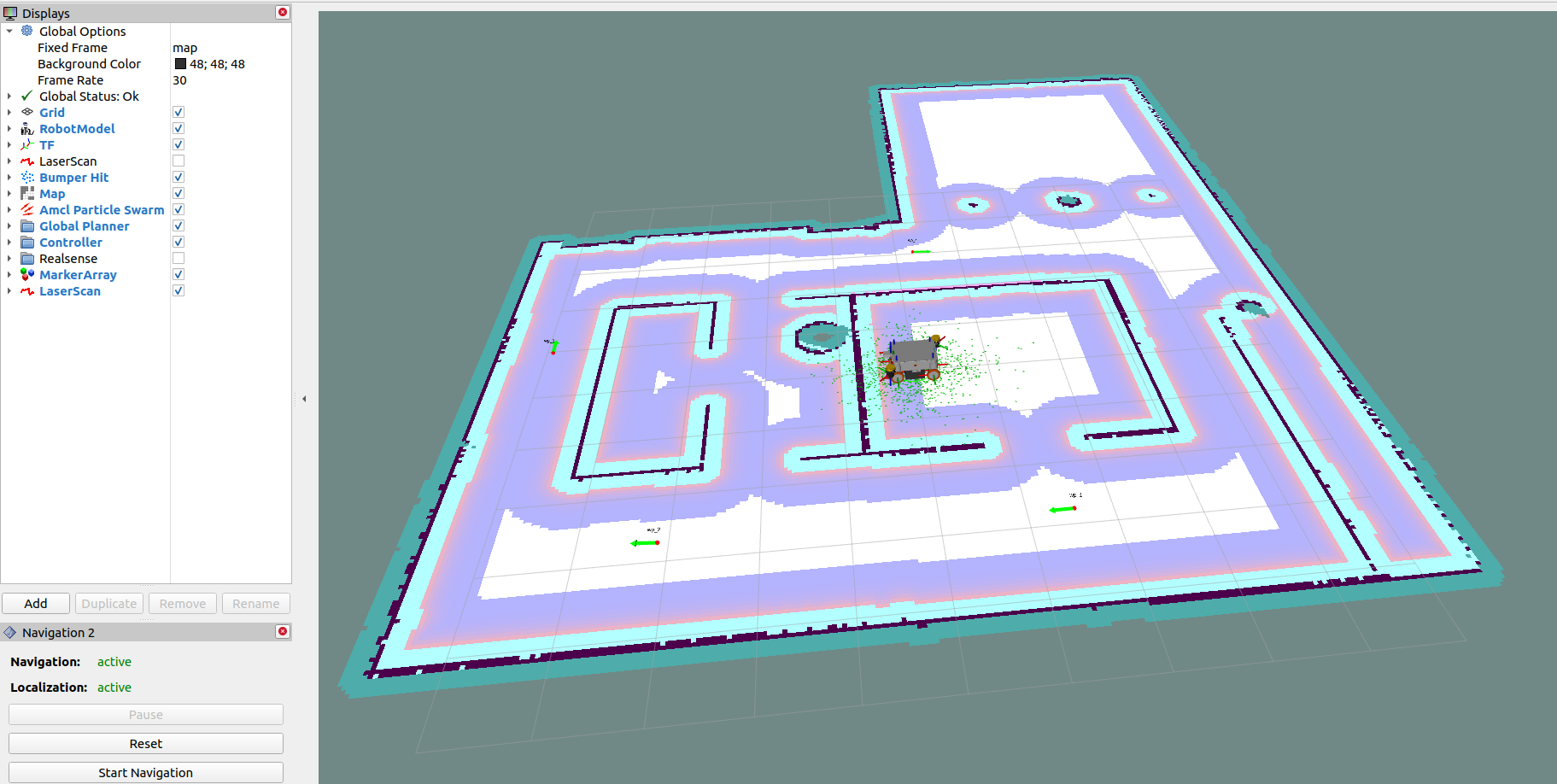
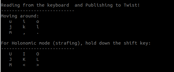
After the launch is completed, the simulation is ready to use.
Robot can be moved using the keyboard as shown in the Image below:
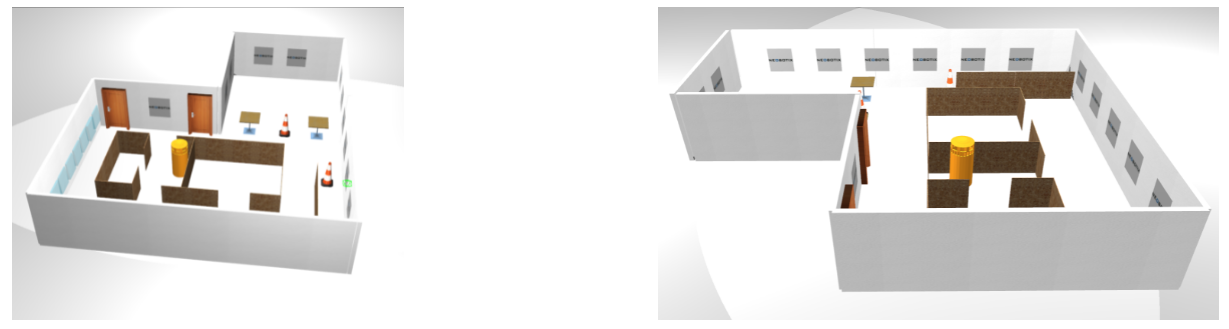
Worlds
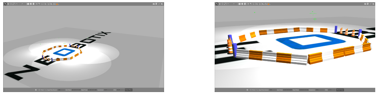
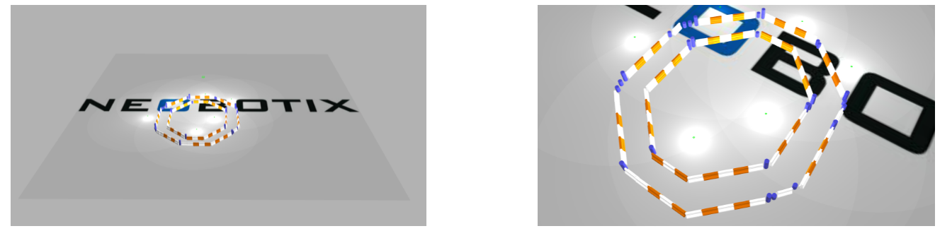
neo_track1
A simple world used to test simple maneuvers. Also this world, allows you to start building and testing your application by spawning the various readily available simulated industrial machineries from gazebo models.
Customizing the Robot Model
LIDAR
We provide options for you to choose between two laser scanners for our robots depending on the application and usage.
- SICK S300
- SICK Microscan
For simulation, you can select you required laser scanners by commenting/uncommenting out the desired part, based on the instructions given in the URDF file.
In the repository for our robot models, we can find the sick_laser urdf file for all the robots, you can modify the desired laser-scanner in that file.
An example to MP-400 is given below.
<!-- SICK S3 sensor: Uncomment/Comment it out if required  -->
<!-- <visual> -->
<!--    <origin xyz="0 0 -0.12" rpy="-1.57 0 3.14" /> -->
<!--            <geometry> -->
<!--                    <mesh filename="package://neo_simulation/robots/mpo_500/meshes/SICK-S300.dae" scale="0.001 0.001 0.001" /> -->
<!--            </geometry> -->
<!--</visual> -->
<!--<collision> -->
<!--    <origin xyz="0 0 0" rpy="-1.57 0 3.14" /> -->
<!--            <geometry> -->
<!--                <mesh filename="package://neo_simulation/robots/mpo_500/meshes/SICK-S300.dae" scale="0.001 0.001 0.001" /> -->
<!--            </geometry>  -->
<!--   </collision>  -->
<!-- Microscan 3 sensor: Uncomment/Comment it out if required  -->
<visual>
        <origin xyz="-0.0 0 -0.06" rpy="1.57 0 0" />
<geometry>
        <mesh filename="package://neo_simulation/robots/mpo_500/meshes/SICK-MICROSCAN3.dae" scale="0.001 0.001 0.001" />
</geometry>
</visual>
<collision>
        <origin xyz="-0.0 0 -0.06" rpy="1.57 0 0" />
<geometry>
        <mesh filename="package://neo_simulation/robots/mp_500/meshes/SICK-MICROSCAN3.dae" scale="0.001 0.001 0.001" />
</geometry>
</collision> -->
IMU
We also provide an option of IMU. Add, Remove or Adjust the position of IMU based on your requirements. An example is given below.
<!--+++++++++++++++++++ IMU ++++++++++++++++++++++++-->
<!-- Comment or uncomment based on your requirement -->
  <xacro:include filename="$(find neo_simulation)/robot_model/mmo_700/urdf/xacros/imu.xacro" />
  s<xacro:imu name="imu_1" parent="base_link">
    <origin xyz="0.100 0 0.300" rpy="0 0 3.14" />
  </xacro:imu>
There will be other sensors added and further developments will be updated.