

Dimensions and Pinout
Dimensions
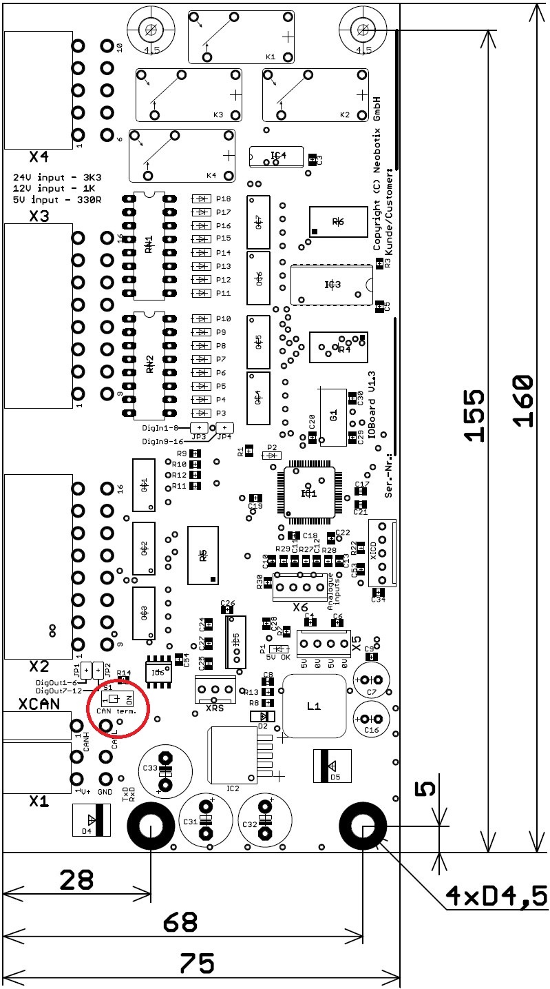
Dimensions of the IOBoard and switch for CAN terminating resistor
Note
The resistor arrays for the digital inputs must be chosen according to the used high level voltage!
| 5V | 330Ω |
| 12V | 1kΩ |
| 24V | 3.3kΩ |
Tip
Set switch S1 to ON to activate the CAN terminal resistor.
Pinout
Details on the connectors can be found at Connectors.
Connector X1
Würth Elektronik, MPC4, 4 pins
Use this plug to connect the power supply and the CAN bus.
| Pin | Description |
|---|---|
| 1 | Power supply |
| 2 | CAN High |
| 3 | Ground |
| 4 | CAN Low |
Connector X2
Würth Elektronik, MPC4, 16 pins
This connector is used for the common ground lines of the optocoupled inputs and outputs and for all signal lines of the digital outputs.
| Pin | Description |
|---|---|
| 1 | Input ground 2 (digital inputs 9 – 16, JP4) |
| 2 | Output ground 1 (digital outputs 1 – 6, JP1) |
| 3 | Digital output 12 |
| 4 | Digital output 9 |
| 5 | Digital output 8 |
| 6 | Digital output 6 |
| 7 | Digital output 4 |
| 8 | Digital output 2 |
| 9 | Input ground 1 (digital inputs 1 – 8, JP3) |
| 10 | Output ground 2 (digital outputs 7 – 12, JP2) |
| 11 | Digital output 10 |
| 12 | Digital output 11 |
| 13 | Digital output 7 |
| 14 | Digital output 5 |
| 15 | Digital output 3 |
| 16 | Digital output 1 |
Tip
Use the solder jumpers JP1 to JP4 to connect the ground lines of the digital inputs and outputs directly to the ground line of the supply voltage.
Connector X3
Würth Elektronik, MPC4, 16 pins
The 16 digital inputs are connected to this plug, indicated by LEDs.
Note
Please use the correct limiting resistors!
| Pin | Description |
|---|---|
| 1 | Digital input 16 |
| 2 | Digital input 14 |
| 3 | Digital input 12 |
| 4 | Digital input 10 |
| 5 | Digital input 8 |
| 6 | Digital input 6 |
| 7 | Digital input 4 |
| 8 | Digital input 2 |
| 9 | Digital input 15 |
| 10 | Digital input 13 |
| 11 | Digital input 11 |
| 12 | Digital input 9 |
| 13 | Digital input 7 |
| 14 | Digital input 5 |
| 15 | Digital input 3 |
| 16 | Digital input 1 |
Connector X4
Würth Elektronik, MPC4, 8 pins
Use this plug to connect to the four isolated relay outputs. The maximum current on each contact is 2 A.
| Pin | Description |
|---|---|
| 1 | Relay 4: Common |
| 2 | Relay 4: Normally closed |
| 3 | Relay 3: Common |
| 4 | Relay 2: Normally open |
| 5 | Relay 1: Normally open |
| 6 | Relay 4: Normally open |
| 7 | Relay 3: Normally closed |
| 8 | Relay 3: Normally open |
| 9 | Relay 2: Normally open |
| 10 | Relay 1: Normally open |
Connector X5
TE Connectivity, HE14, 4 pins
The IOBoard’s internal 5 V logic supply is available on this connector.
| Pin | Description |
|---|---|
| 1, 3 | Ground |
| 2, 4 | 5 V (max. 500 mA) |
Connector X6
TE Connectivity, HE14, 4 pins
This connector provides four analogue inputs for voltages from 0 V to 5 V, relative to the ground level of the IOBoard.
| Pin | Description |
|---|---|
| 1 | Analogue input 1 |
| 2 | Analogue input 2 |
| 3 | Analogue input 3 |
| 4 | Analogue input 4 |
Connector XCAN
Würth Elektronik, MPC4, 2 pins
The CAN bus may be continued from this connector.
| Pin | Description |
|---|---|
| 1 | CAN High |
| 2 | CAN Low |
Connector XRS
TE Connectivity, HE14, 3 pins
This connector provides access to the IOBoard’s RS-232 interface.
| Pin | Description |
|---|---|
| 1 | Ground |
| 2 | TxD (IOBoard transmit line) |
| 3 | RxD (IOBoard receive line) |