

Configuration
The best way to configure and optimise the drive amplifiers is by using the interface software Composer which is provided for free download from the homepage of the manufacturer Elmo Motion Control. The latest version can be found at:
https://www.elmomc.com/product/composer/
It is recommended to connect the computer that runs the Composer to the amplifier by a standard RS-232 serial connection (COM port). The appropriate configuration cable can be supplied on request.
The drive amplifiers are configured with general purpose settings and ready for operation. Before the OmniDriveModule can be used in a mobile robot, the communication parameters have to be adjusted according to the features of the control system.
If extraordinary kinematics are to be realised or if the modules are to be used under extreme conditions (very heavy vehicle or payload, uneven or soft floor, asymmetric centre of gravity, …) it might be necessary to adjust the control loop parameters of some or all amplifiers. Please contact Neobotix in such cases.
Connecting to the Amplifiers
After installing and starting the Composer the start dialogue will appear. Connect the computer to the amplifier by using the configuration cable and turn on the power supply of the amplifier.
Note
Please be careful to actually connect to the amplifier which you currently want to access.
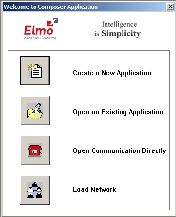
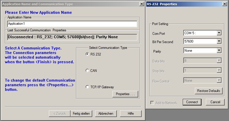
Choose Open Communication Directly to open the communication settings dialogue. After selecting RS 232 as interface and clicking Properties you can select the COM port that you are using. Please select a baud rate of 57600 Bit Per Second and click Connect. The dialogue should close and the configuration toolbox, called Smart Terminal, should appear.
In case you cannot connect to the amplifier, please check the following:
- Amplifier power: Is the amplifier connected to a sufficient power supply and is the power supply turned on? In case the module is connected to a laboratory power supply: Is the current limit high enough to provide the inrush current and a sufficiently fast rise of the logic supply voltage?
- Cable: Is the computer actually connected to the correct amplifier? When handling several drives in a row it sometimes happens that only the power supply is connected to the next module while the configuration cable is still plugged to the previous module.
- Baud rate: The baud rate of the serial connections has been changed to 57.6 kBaud to make working with the modules more convenient. The default baud rate of the Composer is only 19.2 kBaud.
- COM port: Try other COM port numbers. If a USB-to-serial converter or a similar device is used, please check which number has currently been assigned to the interface. Close the Composer, re-connect the converter and restart the Composer.
Use the button Disconnect on the right end of the main toolbar to close the connection to the amplifier. Disconnect button is shown below:

Handling Different Configurations
There are basically three ways of handling different configurations.

Main buttons: Create New Application, Open Existing Application, Save Application (f.l.t.r.)
Saving the Current Configuration
After connecting to an amplifier the current configuration is automatically uploaded to the Composer and can be saved in a file by clicking the button Save Application in the top left corner of the main window. The Composer will always ask whether the current configuration should also be written to the amplifier’s non-volatile memory or if it should only be written to a file on the computer.
A Save-As-dialogue will always appear. If the configuration has been saved before (in the current session), the last used file name will be selected automatically but will also automatically have an extension indicating the currently used interface. To avoid having duplicate files please select the appropriate file manually before clicking Save.
Any changes to the configuration on the amplifier can also be written to the non-volatile memory without creating a file on the computer. Simply type “sv” into the command line of the Smart Terminal and hit Enter or click on Send.
Using an Existing File
To use a backup file simply click the button Open Existing Application, select the file and click Download in the open dialogue. In case the current interface differs from the settings stored in the file, you will need to open the properties dialogue by clicking Change in the Communication Info area of the file open dialogue.
After the connection has been established successfully, the configuration is downloaded to the volatile memory of the amplifier. To save the configuration permanently, please refer to the previous section.
The motor specific commutation parameters are also stored in the configuration file. This means that any known motor can be run by any amplifier after downloading the correct file to the amplifier. It also means that after connecting a new motor to any amplifier, the unique commutation parameters of the new motor have to be determined even if all other settings that are already saved in the amplifier may remain unchanged. Please contact Neobotix if you intend to replace the motor.
Creating a New Configuration
All motor parameters can be defined anew by using an integrated wizard. Since the OmniDriveModules are not meant to be run with different motors, it is not recommended to modify any settings with this feature.
In case you intend to modify the drives or need any further assistance please contact Neobotix.
Basic Settings
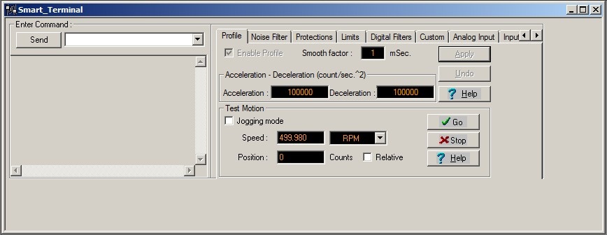
The Smart Terminal of the Composer shows all the basic settings that can easily be changed. In case you need to modify any other settings or need in-depths information, please refer to the documentation on the Elmo MC homepage or contact Elmo MC or Neobotix directly.
The communication settings can be changed by entering the command “PP” plus an index number in square brackets in the command line at the top left of the Smart Terminal. Enter the command and either hit enter or click the Send button to read the current value. Add the equals sign and the new value right after the command to change a setting.
The following commands may be necessary:
| Command | Description | Common values |
|---|---|---|
| PP[2] | RS-232 baud rate | 4: 57600 Baud (Default) |
| 3: 38400 Baud | ||
| 2: 19000 Baud | ||
| PP[13] | CAN ID | 1-8 |
| PP[14] | CAN baud rate | 0: 1000 kBaud (Default) |
| 1: 500 kBaud | ||
| 2: 250 kBaud | ||
| PP[15] | CAN group ID | 1 – 128 (Default: 30) |
Advanced Settings
The motor must be deactivated for some settings to be applied. Use the button Stop & Motor Off to deactivate the motor.

Acceleration and Deceleration
The maximum permitted acceleration and deceleration can be set by editing the two according fields in the tab Profile of the Smart Terminal and clicking Apply. These values are the limiting values and will be used by the internal control loop of the amplifier. The actual acceleration and deceleration in normal operation is mainly determined by your motion control software and will be (and should be) significantly lower.
Speed Limits and Stop Deceleration
Several speed limits can be set on the tab Limits, sub tab Velocity. The Command limits define the velocity range that will be accepted by the amplifier. Motion commands with velocities exceeding this range will be rejected.
The Feedback velocities define the range in which the motor is allowed to operate without raising an error. Therefore the Feedback limits should be set wider than the command limits.
The Stop deceleration is the deceleration that is used when a stop command is sent to the amplifier. This deceleration can be much higher than the values defined as normal acceleration and deceleration. It is meant to provide the fastest yet safest stopping of the axis in case of an emergency.
Control Loop Parameters
The internal parameters of the velocity and position control loop can be changed in the Digital Filters tab.
The values of the current control loop should not be changed manually.
In the unlikely case that the behaviour of the OmniDriveModule does not meet the application’s requirements the internal parameters may be changed carefully. Please consult your local Elmo Motion Control department before modifying these values.
Testing and Debugging
The Test Motion area in the Profile tab can be used to move the motor under manual control for testing purposes. Activate Jogging mode to make the motor rotate continuously with the given Speed, or deactivate the check-box to move the motor to the given Position. Simply click the Go button to start the motion and Stop to set the velocity back to zero.
The Composer also offers a function to record high definition measurements of the motor’s movements and to plot these data graphically. Please contact Neobotix or Elmo Motion Control if you need further information on this topic.