

Electrical Installation
Power Supply
Main Power
Both drive amplifiers are connected to common supply lines. Use the following components for the power supply:
- Plug: Würth Elektronik, Series 351 WR-TBL, 691 351 500 003
- Plug (alternative): Phoenix Contact, MSTB 2,5 HC/ 3-ST, 1911868
- Power cable: H07V-K or better, 2,5 mm² or bigger
- Logic supply cable: H05V-K or better, 0,5 mm² or bigger
The internal logic unit of the drive amplifiers can be powered independently from the main power supply. In case of an emergency stop the amplifiers will still be running, keeping track of the motor position and communicating on the CAN-bus.
Tip
By default the OmniDriveModule is configured for 24 V logic supply voltage. Please contact Neobotix if you want to use other supply voltages.
The pin assignment is as follows:
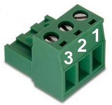
| Pin | Function | Voltage / VDC | Description |
|---|---|---|---|
| 1 | Common ground | 0 | Common return line |
| 2 | Motor power supply | 20 – 59 | Main power supply, may be switched off |
| 3 | 24V logic supply | 11 – 30 | Auxiliary supply, not to be switched at stop |
Position Switch
If 24 V are used as logic supply voltage, the inductive position switch of the orientation drive is powered directly from the amplifiers’ PCB. If different voltages are used, they must be connected to a common ground.
Attention
The ground line of the digital input is by default connected to the common ground of the amplifier power supply. In case independent supply voltages are required, please contact Neobotix.
Use the following components for the power supply of the switch in case you are not supplying 24 V for the amplifiers’ logic:
- Housing: Würth Elektronik, MPC4, receptacle, dual row, 2 circuits, 649002113322
- Contacts: Würth Elektronik, MPC4, crimp terminal female, 18-24 AWG, 64900613722DEC
The pin assignment is as follows:
| Pin | Function | Voltage / VDC | Description |
|---|---|---|---|
| 1 | Supply | 24 | Position switch power supply |
| 2 | Ground | 0 | Return line |
Brakes
The servomotors can optionally be equipped with fail-safe brakes that need to be released while the motor rotates. A 24 V supply capable of providing 0.75 A is required for the brake.
Use the following components for the power supply of the brakes:
- Housing: Molex, series KK receptacle 2 circuits, 22-01-2021
- Contacts: Molex, series KK crimp terminal 22-30 AWG, 08-50-0032
The pin assignment is as follows:
| Pin | Function | Voltage / VDC | Description |
|---|---|---|---|
| Ground | 0 | Return line | |
| Supply | 24 | Brake power supply |
Communication Interfaces
CAN
Both drive amplifiers are connected to the PCB’s CAN-bus connector. Please use the following components for the CAN-bus connection:
- Housing: TE Connectivity, HE14 receptacle double row 8 circuits, 281839-4
- Contacts: TE Connectivity, HE14 crimp terminal female 28-24 AWG, 182734-2
The pin assignment is as follows:
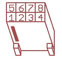
| Pin | Function |
|---|---|
| 1,5 | GND |
| 2,6 | CANL |
| 3,7 | CANH |
| 4,8 | Shield |
If the CAN bus ends at one of the OmniDriveModules a terminating resistor of 120 Ω has to be activated. Please move switch S1 beside the LEDs to position ON.
RS-232
Each drive amplifier has a separate RS-232-interface which can be used for configuration and for communication with the control software.
| Pin | Function | Description |
|---|---|---|
| 1 | GND (Orientation) | Reference ground line (orientation drive) |
| 2 | TxD (Orientation) | Transmit line (orientation drive) |
| 3 | RxD (Orientation) | Receive line (orientation drive) |
| 4 | GND (Traction) | Reference ground line (traction drive) |
| 5 | TxD (Traction) | Transmit line (traction drive) |
| 6 | RxD (Traction) | Receive line (traction drive) |
Digital-I/Os
The drive amplifiers each feature 6 digital inputs, 2 digital outputs and 1 analogue input which may be used for special functions if required. They can be assigned to predefined functions (torque off, hard stop, etc.) or be accessed by the user program running on the amplifier. Their current state can also be read by the control software via the CAN-bus or the serial interface.
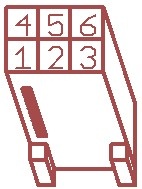
The connectors X2 and X5 of the PCB provide easy access to three of the digital inputs and one digital output. These inputs can be equipped with a limiting resistor if the signal voltage is higher than 5 V. The positions for these are marked “Rin1”, “Rin2” and “Rin3” and are located right beside the connectors.
Please keep in mind that the limiting resistor has to be bridged if the default signal level of 5 V is used.
The digital input 1 of the orientation drive amplifier is connected to the output of the position switch and cannot be used for customised functions.
Tip
The ground line of the digital inputs of the orientation drive amplifier is by default tied to the common ground of the amplifier power supply. In case independent voltage levels are required, please contact Neobotix.
The return line of the digital inputs of the traction drive amplifier can also be tied to the common ground by bridging the solder jumper marked “G←I-”.
The motors’ encoder signals are also available at the IO connectors. They can for example be used for motion monitoring by an external safety device.
Furthermore the IO connectors provide power supply for additional low power sensors. The module’s logic supply voltage is available at pins “VL” (supply) and “G” (ground).
Further information can be found in the documentation of the drive amplifier “Whistle” on the homepage of Elmo Motion Control.
Use the following components for the I/O connection:
- Housing: TE Connectivity, HE14 receptacle double row 12 circuits, 281839-6
- Contacts: TE Connectivity, HE14 crimp terminal female 28-24 AWG, 182734-2
| Pin | Function | Description |
|---|---|---|
| 1 | A+ | Channel A of the TTL motor encoder, for motion monitoring |
| 2 | B+ | Channel A of the TTL motor encoder, for motion monitoring |
| 3 | O- | Emitter contact of the optocoupler of digital output 1 |
| 4 | G | Main ground |
| 5 | I- | Common ground of the digital inputs |
| 6 | I2 | Digital input 2 (mind the limiting resistor) |
| 7 | A- | Channel A (inverted) of the TTL motor encoder, for motion monitoring |
| 8 | B- | Channel B (inverted) of the TTL motor encoder, for motion monitoring |
| 9 | O1 | Collector contact of the optocoupler of digital output 1 |
| 10 | VL | Logic supply (output) |
| 11 | I1 | Digital input 1 (mind the limiting resistor) |
| 12 | I3 | Digital input 3 (mind the limiting resistor) |
Motion Monitoring
On request the connectors can be prepared to provide direct access to the encoder signals of the traction and / or orientation motor from outside.
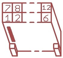
This option will change the pin assignment as follows.
| Pin | Function | Description |
|---|---|---|
| 1 | O- | Emitter contact of the optocoupler of digital output 1 |
| 2 | B+ | Channel A of the TTL motor encoder, for motion monitoring |
| 3 | A+ | Channel A of the TTL motor encoder, for motion monitoring |
| 4 | O1 | Collector contact of the optocoupler of digital output 1 |
| 5 | B- | Channel B (inverted) of the TTL motor encoder, for motion monitoring |
| 6 | A- | Channel A (inverted) of the TTL motor encoder, for motion monitoring |
This option requires different connector housings:
TE Connectivity, HE14 receptacle double row 6 circuits, 281839-3
Enable Lines
On request the drive amplifiers can be configured to have two 24 V enable lines. The signals can be integrated into the CAN bus cable and then be conveniently patched through to all OmniDriveModules.
This option uses digital inputs 2 and 3 which then are no longer available for other functions.
Attention
Please note that this feature is not safety approved.
The pin assignment of the CAN bus connector changes as follows:
| Pin | Function |
|---|---|
| 1,7 | GND |
| 2,8 | CANL |
| 3,9 | CANH |
| 4,10 | Shield |
| 5,11 | Enable1 |
| 6,12 | Enable 2 |
This option requires the same connector housings as the digital I/Os.