

Charging Stations
Inductive Wallbox
General Information
All ROX robots and some of the older robot types can be charged via the inductive charging station Wallbox. This is possible both for robots with AGM batteries as well as LiFePO4 batteries. The charging station works completely wear-free and the charging curve is automatically adapted to the battery type used by the robot controller. This makes it ideal for in-process charging during the ongoing operation in order to maximize the working time of the autonomous robot.
Note
The efficiency of inductive fast charging of LiFePO4 batteries is significantly higher and the charging time is considerably shorter than with AGM batteries. We therefore expressly recommend the use of LiFePO4 batteries if automatic charging via the inductive charging station is desired.
Warning
The wired battery charger and the inductive charging station must never be used at the same time! Despite protective features in both devices there is a theoretical chance of malfunctions that could potentially lead to severe damage and the destruction of the chargers or the robot.
Tip
To be able to use the inductive charging station, the mobile robot must be switched on and ready for operation. If the robot is switched off, it can only be charged using the wired charger.
Please take this into account when planning your application.
Safety Information
The Neobotix Wallbox features several protective mechanisms and is easy to set up and connect. Nevertheless the following advice must be taken into account to enable safe operation of the Wallbox.
Increased Magnetic Fields
The ROX Wallbox uses strong electromagnetic fields to transmit the charging power to the mobile robot. To prevent harmful effects on people or animals, no living creatures may be in the vicinity of the coils during the charging process. The area marked in yellow in the following illustrations is generally to be regarded as a danger zone.


Danger
Interference with pacemakers!


It is possible to influence the function of a pacemaker within the effective range. Interference with a pacemaker can be life-threatening for the wearer. Persons with pacemakers or metallic implants must not enter the effective range.
Warning
Increased Magnetic Field!
The increased magnetic field can be harmful to living beings. No living creatures may be in the danger zone during the charging process. It is essential to keep the area directly between the robots in the area of the coils clear, as otherwise the permissible exposure limits may be exceeded!
This electromagnetic field only occurs during the charging process and is automatically cancelled when the robot stops charging, is removed from the charging station or is switched off. The field emanates exclusively from the wallbox; the mobile robot itself cannot generate a field.
To be absolutely certain that the area around the wallbox can be entered while a robot is currently at the station, the wallbox’s power cable can simply be unplugged from the socket.
Increased Temperatures
The Wallbox achieves an efficiency that is comparable to conventional, wired chargers. Nevertheless, relatively high power losses occur at high charging outputs, which can lead to the Wallbox and the mobile robot heating up. Especially when using AGM batteries, which can only cope with low charging currents, the efficiency is significantly lower and the heating is noticeably higher.
Warning

The housing of the Wallbox and the front of the mobile robot may have an increased temperature. Do not touch these parts and allow all housings to cool down before working on the system.
Installation
Mechanical Installation
The ROX Wallbox has four rubber feet that give it a secure stand. In principle, it can therefore also be used free-standing in the room. However, in order to minimise access to the danger zone described above and to avoid tripping hazards as well as unintentional movement of the wallbox, it should preferably be placed against a wall and secured to it. For this purpose, the wallbox has a fixing point above the cover. The fixing material is not included in delivery. Please ensure correct installation.

Please consider the following points when planning the charging process and positioning the Wallbox:
- The wallbox and, above all, a charging robot must not be an obstacle or become a tripping hazard. Escape and rescue routes in particular must remain clear according to the applicable safety regulations.
- To approach the Wallbox, the robots require sufficient free travelling distance in front of the charging point. There should be an approach distance of at least 1 metre straight towards the wallbox, if possible 1.5 metres. Otherwise, in unfortunate cases, the lateral offset may not be sufficiently compensated and the efficiency may drop or charging may fail.
- The charging process generates noticeable waste heat due to the high power. The Wallbox should therefore preferably be installed in a cool environment with sufficient airflow. Direct sunlight, waste heat from other machines or air congestion should be avoided.
Electrical Installation
The mains cable of the wallbox can be routed out of the housing either on the left or right. To prevent the cable from being crushed between the wall and the wallbox, the cable can be secured to the inner profile frame of the wallbox using a cable socket and a cable tie. If the cable cannot remain as it is in the as-delivered state and needs to be routed to the opposite side, proceed as follows:
- Cut the originally used cable tie. Take care not to damage the cable!
- Route the cable inside the panelling and underneath the electronics housing to the other side of the wallbox.
- Use the enclosed additional cable tie to secure the cable to the cable socket.


The Wallbox can be connected to a normal AC power socket. If extension cables must be used, they must be designed for at least the rated power of the Wallbox.

The Wallbox is a protection class I device and requires a protective earth connection for the mains cable.
Note
Install a common trip type circuit breaker with a rating of 16A. Additionally, ensure that the breaker has a short-time withstand current limit of minimum 10 kA.
Warning
In case of internal isolation failures, this product may cause a DC current in the PE conductor. To protect against electrical shock, only use an RCD (Residual-Current Device) of Type B on the supply side of the Wallbox. It is important to note that no other equipment should be connected to this specific RCD.
The Charging Process
Basic Function
The basic procedure for inductive charging is as follows.
The robot is positioned at the optimum distance a few millimeters in front of the Wallbox.
The application control initiates charging via a software command.
A data connection between robot and station is established automatically and the charging process begins. The robot is set to charging state with reduced power use and all movements stopped. Do not press any emergency stop button while charging!
Charging may be stopped due to the following events or measures:
The batteries are fully charged. The robot recognises the end of charging, reports it to the higher-level control system if necessary and automatically stops charging or switches to conservation charging mode.
Charging is ended by the application control. This can happen after a predefined time has elapsed or when the main application reaches a certain state. The charging process is ended by the robot and it switches back to pure battery operation.
One of the emergency stop buttons on the robot is pressed. In this case, the robot stops the charging process immediately. It can only be resumed after the button has been unlocked and the emergency stop status has been reset. Charging does not re-start automatically but has to be initiated by the application control.
Note
This is not a certified safety function. If increased safety requirements apply to your application, please contact Neobotix.
The robot is shut down or switched off. In both cases, charging is ended automatically and can only be resumed once the robot has been restarted and is ready for use.
The robot is mechanically removed from the charging station. The charging system recognises when the receiver coil in the robot is too far away from the transmitter coil in the station and then automatically interrupts the charging process. The magnetic field emanating from the charging station is immediately cancelled and cannot be restored until the charging process is properly restarted.
Simple Automatic Operation
For the simplest version of automatic charging, the Wallbox must be installed in a fixed location and the exact robot position for charging must be found manually once. The charging position should be stored as coordinates or as a station.
- The robot moves to this charging position in automatic mode while switching the motion parameters and safety fields.
- Charging is performed as described above.
- The robot moves away from the station and resumes operation.
Note
The collision avoidance parameters and the laser scanners’ safety fields need to be adjusted before the robot can move very close to the station. After leaving the Wallbox these settings must be changed back to the safe default values.
A 3-step approach was found to be best to ensure a reliable docking process. Examples are available in the supplied software package.
Fully Automatic Operation With Contour Detection
To simplify the setup of automatic charging and increase the reliability of the charging process, Neobotix offers a fully automatic solution in which the Wallbox is automatically detected in the environment and approached. This means that minor relocations of the Wallbox, for example due to conversions or cleaning, are no longer a problem. In addition, the corresponding robot position does not have to be determined individually and with millimetre precision for each Wallbox, which saves a considerable amount of time and eliminates careless errors.
In order to use the automatic charging with contour detection, the Wallbox has to be positioned approximately at its intended position. The allowed tolerances in position and orientation depend on the environment conditions. An initial reference position for the robot has to be defined. We recommend a position approximately 2 m in front of the Wallbox. The automatic process is as follows:
- The robot moves to the reference position in automatic mode.
- The automatic function is started by a service call depending on the application setup.
- The robot then tries to recognize the contour of the charging station at the intended position and automatically performs a multi stage docking process.
- Charging is either performed automatically or as described above.
- Depending on the software setup, the robot performs an undocking and moves back to the reference position
- Normal operation can be resumed.
Tip
Contour detection can also be used for other shapes and applications if required. Please contact us if you are interested in this feature.
Technical Data and Miscellaneous Information
Dimensions

| Property | Unit | Value |
|---|---|---|
| Maximum airgap between coils | mm | 30 |
| Maximum airgap between Wallbox and ROX | mm | 15 |
| Maximum allowed misalignment | mm | 30 |
| Nominal efficiency | 93% | |
| Supply voltage | V (AC) | 220-240 |
| Supply voltage frequency | Hz | 50-60 |
| Nominal system power | W | 2800 |
| Rated current of the circuit breaker | A | 16 |
| Residual Current Devise type | B |
Disposal

Defective and disused electrical appliances must not be disposed of with household waste but must be handed in to separate collection points for reuse or recycling.
If you are unable or unwilling to dispose of your old Neobotix Wallbox yourself, Neobotix will be happy to do this for you. You can simply return your Neobotix Wallbox to us or send it to us by post or carrier. Alternatively, we can arrange to collect it from you or send you a shipping label for free return.
You can find further information and contact details on our website.
Legal Notes
The general legal notes can be found at Legal Notes.
RoHS Information

This product complies to the RoHS directives 2011/65/EU (RoHS 2) and 2015/863/EU of the European Parliament and the Council on the restriction of the use of hazardous substances in electrical and electronic equipment.
Automatic Charging Station
The automatic charging station is very robust and can easily be installed and integrated into the robot’s program.
In order to allow a fast and trouble-free docking, there needs to be some free space to each side of the station and to the front. Find a place that can be easily accessed by the robot when it needs to recharge but in which neither station nor robot are obstacles to anybody. A power outlet must be nearby for the battery charger to be plugged in.
Please mind the following when choosing the stations mounting place:
- In order to have the charging contacts on the correct height, the bottom edge of the station’s backplate must be placed directly on the floor.
- The charging station must be mounted to a stable wall. Please contact Neobotix if you need a free-standing charging station.
- The station must be mounted centred at the rear end of a free path that is at least 1.0 m wide.
- When using more than one station, please keep a grid of at least 1.0 m width.
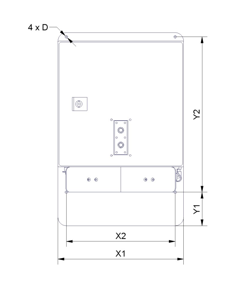
Dimensions
The dimension of the charging station varies depending on the robot. The dimensions can be found in the table below:
| Robot | X1 | X2 | Y1 | Y2 | D |
|---|---|---|---|---|---|
| MP-400 | 300 | 260 | 80 | 370 | 6.6 |
| MP-500 | 300 | 260 | 110 | 360 | 6.6 |
| MPO-700 | 300 | 260 | 192 | 370 | 6.6 |
| MPO-500 | 340 | 320 | 40 | 290 | 6.6 |
After Installation
After installing the charging station please check the height of the charging contacts and if the robot can reach the station without problems.
Attention
Only plug in the power cable after successfully checking these two points. The charging station requires the same power supply as the external battery charger.
To allow automatic charging the battery charger inside the station needs to remain switched on at all times. Despite the open contacts which the robot needs for charging, there is no danger of electric shock or short-circuiting due to the charger’s control mechanism. There will only be a current if the device has detected the correct batteries.
Note
In normal operation, the platform’s charging contacts are disconnected from the batteries by a power relay on the platform’s RelayBoard. This relay can be controlled by software.
Attention
The wear of the electrical components can be reduced by stopping the charging process only after the batteries have been fully charged and the charging current is reduced.
External Battery Charging Station
If the robot is equipped with the battery quick change system the battery set that is currently not in use can be recharged in an external battery charging station.
Place the charging station on the floor and make sure that it will not slip. The station can either be placed directly in front of a wall or can be screwed to the floor.
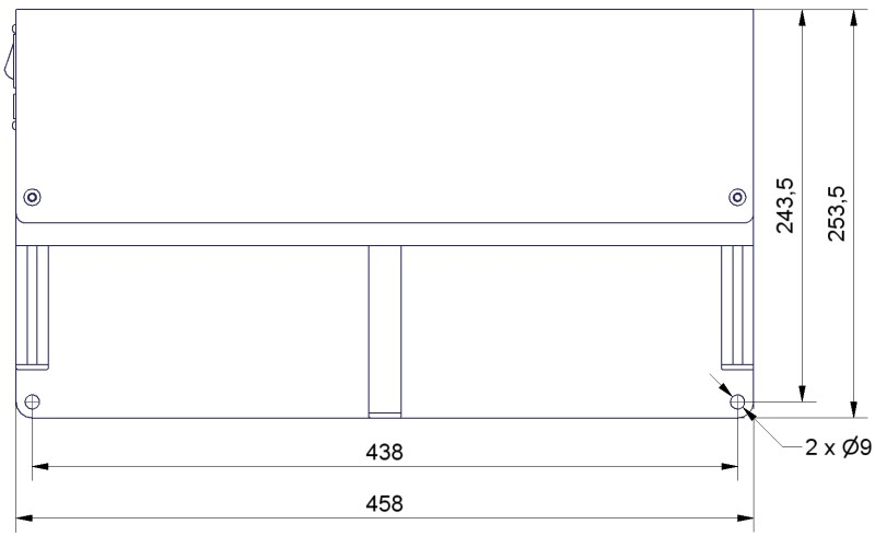
Dimensions of the charging station
Make sure that the input voltage selection switch is set correctly and then connect the charging station to an ordinary power outlet. Before installing any batteries always make sure that the integrated battery charger is switched off. The main power switch is located directly beside the power cable connector.
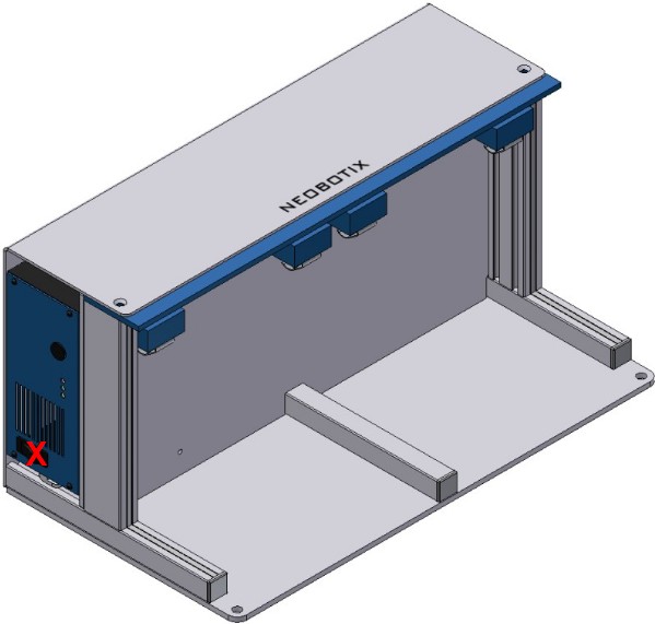
Position of the main power switch (X)
Batteries can only be charged as a complete set of two identical batteries with the same charge level. Place the batteries onto the station’s base plate between the aluminium profiles with the handles on top and the battery contacts facing towards the station’s rear. Then slowly push the batteries into the station until they touch the vertical plate and are flush with the station’s front.
The green LED at the side of the battery charger will light up constantly when the batteries are fully charged. They can remain inside the charging station until they are needed.