Graphical User Interface
Download the GUI here: 32bit, 64bit
Note
Please note that the 64bit version is no longer usable with the latest JRE version!
Introduction
The USBoard-USS4 is provided together with the USBoard-USS4 configuration GUI, a graphical parameter editor.
The USBoard-USS4-GUI requires a PC with:
- RS-232 interface (COM port) and
- Java® Runtime Environment 1.5 or later.
The connection between serial interface and USBoard-USS4 is established by a special cable which can be obtained from Neobotix or self-constructed using the specifications. This cable also connects the USBoard-USS4 with an appropriate power supply. A working supply is indicated by a green LED on the board.
To start the application, simply double-click on the start.bat file.
Make sure to use the program version that matches your operating system.
The GUI can also be used on machines with Linux or Mac OS.
This requires that the Java runtime environment can find the correct RXTX library.
It is also necessary that the user has the permissions needed to access the serial interface.
When using Ubuntu Linux please install the package librxtx-java and add the user to group dialout.
First Steps
Establishing a connection
Before starting a connection via the USBoard-USS4-GUI, please make sure that the USBoard-USS4 is connected
- to the PC’s RS-232 interface and
- to a power supply (LED lights up).
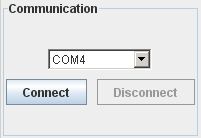
Now select the correct communication port in the application and
click the Connect button, to create the connection.
Receiving data
After establishing a connection, first data will show up. Depending on currently set parameters, measured data are updated automatically in defined interval or can be read manually by clicking the Request buttons. If the measured distance of a sensor falls below its specified warning distance, the value is displayed yellow. In case of under-running the alarm distance, the colour changes to red. As long as any measured distance is below the according warning or alarm distance, the according LED on the USBoard-USS4 will light up and the relay is activated.
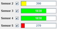
The measured values of the analogue inputs (voltage range 0V – 5V) are displayed as percentages below the distances.
Closing the Connection
To close the connection to the USBoard-USS4, just click the button Disconnect.
Configuring the USBoard-USS4
Communication Settings
In USBoard-USS4-GUI’s left column several parameters regarding the communication settings of the USBoard-USS4 can be defined.
The CAN base ID and transfer rate for communication via the CAN bus can be set in the CAN panel.
The general transmission behaviour can be set in the Transmission Mode panel.
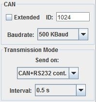
The following table explains the different transmission modes. The interval parameter is only relevant for continuous transmission.
| Transmission mode | Behaviour |
|---|---|
| Request | Send only on request |
| CAN cont. | Send continuously via CAN bus |
| RS232 cont. | Send continuously via RS-232 interface |
| RS232 + CAN cont. | Send continuously via both interfaces |
Configuring the Sensors
Various parameters of the ultrasonic measurement can be set in the right part of the GUI. Each sensor can be activated separately by marking the check-box beside its name. Deactivated sensors send neither ultrasonic impulses nor data. The warning and alarm distance of each sensor can be set in the edit fields to the right of the measurement indicator. The ID and analogue inputs of the USBoard-USS4 are not configurable.
Warning
The USBoard-USS4 is – despite warning and alarm functions – no safety system and can only provide supporting, non-safe information. Never use the USBoard-USS4 for safeguarding of dangerous areas or movements.
Transferring the Configuration
Changed configuration parameters have to be transmitted to the USBoard-USS4 to come into operation. The USBoard-USS4-GUI offers buttons for two available options:

Write to Boardtransfers the parameters to the volatile memory of the USBoard-USS4. After the next restart, the old parameters from the non-volatile memory will be used again.Write to EEPROMwrites the parameters into the non-volatile memory of the USBoard-USS4, so these parameters will be used until they are overwritten by using the same command.
To load the current parameter set from the USBoard-USS4 and display it in the -USS4-GUI, click the Read from Board button.
Please note that all previous changes in the input mask will be lost.
Saving and Loading Configurations
The buttons Save to File and Load from File permit the user to save
the current configuration into a file on the local computer or load it from one.
Simply enter the file name or select an existing file in the dialogue that
appears after clicking either button and confirm by clicking OK.
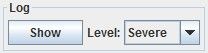
Logging
The USBoard-USS4-GUI writes log files for debugging purposes.
The information that is to be logged while the GUI is running can be chosen
from several different levels between Severe (critical problems only) and
Finest (every action).
The log files are located in the folder log in the same directory that the GUI is in.
A real time display of the currently active log can be opened with the button Show / Hide.