Dimensions and Pinout
Dimensions
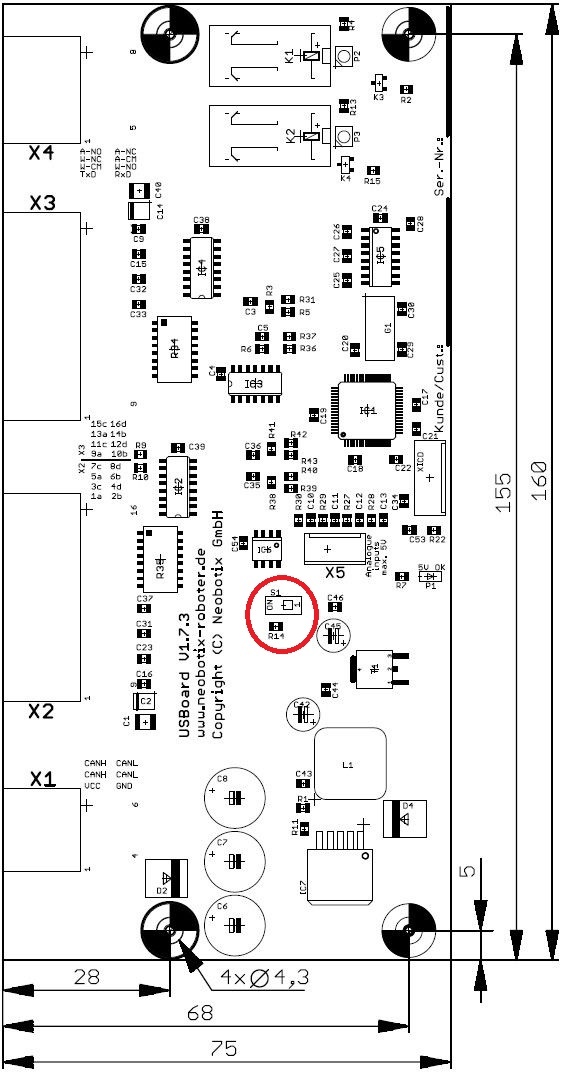
Move S1 to position ON to activate the CAN terminating resistor.
The mounting hole at the bottom right corner is electrically connected to the ground plane of the USBoard-USS4. Please insulate this mounting point if necessary in your installation.
The USBoard-USS4 can be mounted both horizontally and on walls. Please note that when mounted upside down the relays might malfunction. The data output is not affected by the mounting orientation.
Pinout
Tip
More information about these connectors can be found at Connectors.
Connector X1 – WE MPC4, 6-pin
| Pin | Description |
|---|---|
| 1 | Power supply input |
| 2 | CAN High |
| 3 | CAN High |
| 4 | Ground (for both power supply and RS-232) |
| 5 | CAN Low |
| 6 | CAN Low |
Pins 2 and 3 are bridged, as well as pins 5 and 6. This allows two CAN cables (CAN-in and CAN-out) to be connected easily.
Connector X2 – WE MPC4, 16-pin
| Pin | Description |
|---|---|
| 1-4 | Sensor power supply 0 V |
| 5 | Sensor 1 |
| 6 | Sensor 3 |
| 7 | Sensor 5 |
| 8 | Sensor 7 |
| 9-12 | Sensor power supply +8 V |
| 13 | Sensor 2 |
| 14 | Sensor 4 |
| 15 | Sensor 6 |
| 16 | Sensor 8 |
Connector X3 – WE MPC4, 16-pin
| Pin | Description |
|---|---|
| 1 | Sensor 9 |
| 2 | Sensor 11 |
| 3 | Sensor 13 |
| 4 | Sensor 15 |
| 5-8 | Sensor power supply 0 V |
| 9 | Sensor 10 |
| 10 | Sensor 12 |
| 11 | Sensor 14 |
| 12 | Sensor 16 |
| 13-16 | Sensor power supply +8 V |
Connector X4 – WE MPC4, 8-pin
| Pin | Description |
|---|---|
| 1 | RS-232 transmit |
| 2 | Relay “warning distance”, common contact |
| 3 | Relay “warning distance”, normally closed contact |
| 4 | Relay “alarm distance”, normally open contact |
| 5 | RS-232 receive |
| 6 | Relay “warning distance”, normally open contact |
| 7 | Relay “alarm distance”, common contact |
| 8 | Relay “alarm distance”, normally closed contact |
Analogue input connector – TE Connectivity HE14, 4-pins
| Pin | Description |
|---|---|
| 1 | Analogue input 1 |
| 2 | Analogue input 2 |
| 3 | Analogue input 3 |
| 4 | Analogue input 4 |
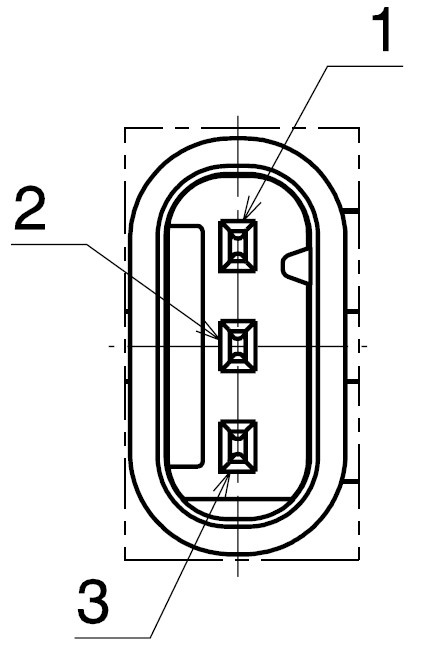
Sensors – Housing: TE 1-1718644-1, Contacts: TE 1452668-1
| Pin | Description |
|---|---|
| 1 | Send / receive |
| 2 | Sensor power supply 0 V |
| 3 | Sensor power supply +8 V |