

Configuration
Basic Features
Sensor Configuration
The basic settings of the ultrasonic sensors can be changed right in the main measurement view.
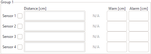
Activation
Set the tick in the checkbox to activate the according sensor. Deactivated sensors will not be triggered by the USBoard-USS5, will not send an ultrasonic pulse and the board will not wait for an echo.
Tip
Deactivate all channels that are not in use. This will reduce the cycle time for handling all sensors and provide updated measurements as fast as possible.
If a sensor is not physically connected to the USBoard-USS5 but is marked as active the GUI will indicate this case by displaying “N/A” instead of a measurement value.
Thresholds
Every sensor has one warning and one alarm threshold. As soon as any active sensor measures a distance that is below the threshold the corresponding relay will be switched. The relays remain in active state as long as the measurement of at least one sensor is below its associated limit. Setting a threshold value of 0 will deactive the function for this sensor.
Only integer values are accepted, indicating the distance in centimetres.
Handling Configurations
You can use the buttons in the functions area to save configurations to your local computer or to reuse them later. When connected you can also transfer a new configuration to a USBoard-USS5 or read the current one from the board.

Most of these functions are self-explanatory but some details should be kept in mind.
- Whenever you transfer a configuration (from file to GUI, from GUI to USBoard-USS5 or the other way round) the data on the receiving end will be overwritten. There is no Undo function.
- Use Write to Board to quickly test new settings. After restarting the USBoard-USS5 these changes will be lost and the configuration from the EEPROM memory will be used instead.
- Using Write to EEPROM stores the configuration in the non-volatile memory and also applies it immediately.
- Read from Board will only read the settings that are currently in use. These may differ from the configuration stored in the EEPROM.
Advanced Features
Please select the tab Configuration to change the view in the data area.
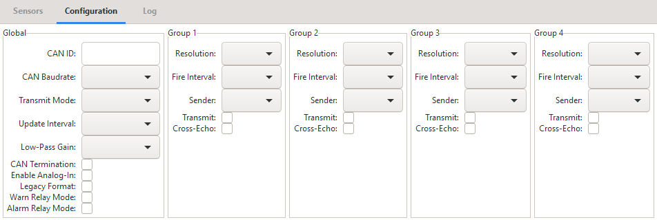
Global Settings
The box Global on the left contains communication and general settings.
- CAN ID
- The base address of the USBoard-USS5 for CAN bus communication.
- CAN Baudrate
- The CAN bus data rate.
- Transmit Mode
- Sets the output mode of the board. Request means that the USBoard-USS5 will only send messages on request. In all other settings it will send out messages automatically via the selected interface.
- Update Interval
- Defines the cycle time for sending messages in automatic sending mode.
- Low-Pass Gain
- The low pass filter feature can be used to smoothen the measurements and to prevent single, potentially faulty, readings from immediately switching the relays. Each new measurement of a sensor is added to the output value according to the filter’s weight. A setting of 0.3 means that the output is calculated from 70% of the previous value and 30% of the new measurement. A setting of 1.0 means that each new measurement is directly used as output value while the old value is discarded, in effect deactivating the filter.
- CAN Termination
- In case of the USBoard-USS5-IP the CAN bus terminating resistor can be activated here. This parameter is without function in the normal USBoard-USS5.
- Enable Analog-In
- Activates the use of the four analogue inputs. If your application requires very short cycle times and does not use these inputs it is recommended to disable the analogue inputs completely.
- Legacy Format
- Enables the use of the USBoard V1 protocol. This makes the USBoard-USS5 compatible to older applications but disables some features.
- Warn Relay Mode
- When checked, blocked sensors do not affect the warning relay, which can still be switched by the remaining functional sensors. Use this mode only if blocked sensors do not reduce the operational safety of your system. If unchecked, the warning relay is switched on as soon as a single sensor is blocked, regardless of the readings measured by the other sensors. Use this mode to indicate all cases of blocked sensors.
- Alarm Relay Mode
- Equivalent to Warn Relay Mode but affecting the alarm relay.
Sensor Group Settings
The ultrasonic sensors are grouped in sets of four sensors each. The settings in this area always apply to all sensors of a group. Different groups can have completely different configurations.
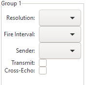
- Resolution
- The measurement data can be sent in four different resolutions: 1 cm, 0.5 cm, 0.25 cm or 0.125 cm.
- Fire Interval
- The time between firing two sensors can be adjusted to avoid unwanted echos from earlier pulses. The minimum time a sensor needs to send a pulse and evaluate the echo is 10 ms. The minimum firing interval of 10 ms offers the fastest cycle time and is designed for a relatively short distance detection up to 150 cm. When the object is placed at a distance of more than 150 cm, there is not enough time for the sensor to receive the reflected echo within 10 ms. To provide enough time for the reflected echo to be received by the sensor at the maximum distance the default firing interval is 20 ms.
- Sender
- If the group operates in cross-echo mode the pulse sending sensor can be selected here.
- Transmit
- Includes the group into the data output.
- Cross-Echo
- Switches the group from normal, sequential operation mode to cross-echo mode.