

First Steps
The GUI Layout
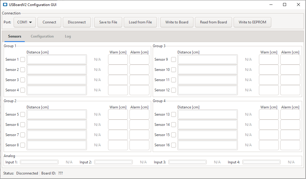
The graphical user interface is divided into three main areas: the main functions area at the top, the central data area and the footer.
The Functions Area
The functions area is divided into three groups.

On the left you can find the basic functions to establish a connection to the USBoard-USS5 and also to disconnect again.
- Port:
- Here you can select the interface that will be used to communicate with the USBoard-USS5. When plugging in the USB cable the operating system will automatically add a virtual COM port that can be selected here.
- Connect
- Opens the selected interface and establishes a connection to the USBoard-USS5.
- Disconnect
- Closes an open connection to a board.
Use the buttons in the central group to save the current USBoard-USS5 configuration into a file on your local computer or to load a configuration from such a file.
- Save to File
- Saves the configuration from the GUI into a file on your computer.
- Load from File
- Loads a configuration file and changes the GUI settings accordingly.
On the right you can find the buttons to transfer the current settings from the GUI to the USBoard-USS5 and to read the board’s configuration into the GUI.
- Write to Board
- Transfers the parameters to the volatile memory of the USBoard-USS5. After the next restart, the old parameters from the non-volatile memory will be used again.
- Read from Board
- Reads the current configuration from the USBoard-USS5 and displays it in the GUI.
- Write to EEPROM
- Writes the parameters into the non-volatile memory of the USBoard-USS5. These settings will be activated after a restart of the board.
The Data Area
The central data area features three different views that can be activated by clicking on the three tabs on top.
- Sensors
- This view visualises the readings of the active sensors and displays their warning and alarm thresholds.
- Configuration
- Here you can adjust the communication parameters and configure the sensors’ behaviour.
- Log
- The log lists system messages related to certain events.
Visualizing Measurements
Ultrasonic Sensors
The ultrasonic sensors are grouped by four, with each group being displayed in its own box within the data area.
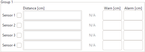
The check boxes next to the sensor numbers indicate whether a sensor is active. Only active sensors are triggered and read by the USBoard-USS5.
Tip
Deactivating sensor channels that are not in use will reduce the cycle time for reading all sensors and update measurements faster. Deactivated channels will be skipped by the USBoard-USS5 without waiting for an echo.
The warning and alarm thresholds of each sensor are displayed on the far right. The current distance measurements are shown as coloured bars and numerical values in the centre of the box.
Note
The USS5 sensors have an upper and a lower measurement limit. If an object is detected closer than the lower limit the message “BLOCKED” is shown instead of the measurement value. If no object can be detected within the measurement range at all the message “TOO FAR” will be shown.
Analogue Inputs

The measurements of the analogue inputs can be found below the ultrasonic sensor display. The analogue input values are also shown both as numerical value and as bars. The bars indicate the ratio of the current input voltage relative to the maximum input voltage.