

Operating Elements
The figures below show the sides of the MP-400 and the most important operating elements.
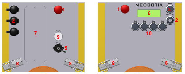
Operating Elements
| 1 | Emergency stop buttons |
| 2 | Key switch |
| 3 | Brake release button |
| 4 | USB / Ethernet sockets |
| 5 | Charging socket |
| 6 | LC-Display |
| 7 | Maintenance access (optional) |
| 8 | Cover fasteners |
| 9 | LED “charging” |
| 10 | Keypad |
Emergency Stop Buttons
When one of these buttons is pressed the robot is immediately set to emergency stop. All drives are disconnected from power supply and the fail-safe brakes are engaged. This state can be reset by unlocking the emergency stop buttons and turning the key switch clockwise for a few seconds.
Key Switch
See Key Switch.
Brake Release Button
Pressing this button will open the motors’ brakes thus allowing the robot to be moved manually even while it is turned off.
Tip
If the control software is running and the emergency stop buttons are not pressed, the motor amplifiers will still stabilise the robot’s position when pressing the brake release button. In this case at least one of the emergency stop buttons must be pressed before the robot can be moved manually.
Charging Socket and Indicator LED
The battery charger is integrated into the robot. To charge the robot plug in the power cable and fasten it properly before connecting it to a normal AC power outlet. The white charging indicator LED will light up until charging is finished. The robot can remain connected to the power outlet even with the batteries fully charged.
LC-Display
This display shows the most important status information. A detailed description of the LCD can be found in LC Display.
Access to the On-Board Computer
The maintenance hatch provides access to the computer interfaces. A USB socket behind one of the black caps can be used to connect a wired joystick for temporary manual control in case there is no receiver for the wireless joystick plugged in already. An Ethernet socket is also available in case the WiFi connection is temporarily unavailable.
Keypad
The keypad can be used for simple input and predefined commands. By default it is without function and has to be interpreted by the application control software.
Pressing the Info button shows technical details of the robot on the LCD as described at LC Display.